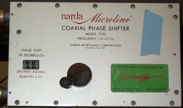
Phase shifter. Readout on left; input port upper left corner, output lower left corner.
1.1 Source of Low-Level RF
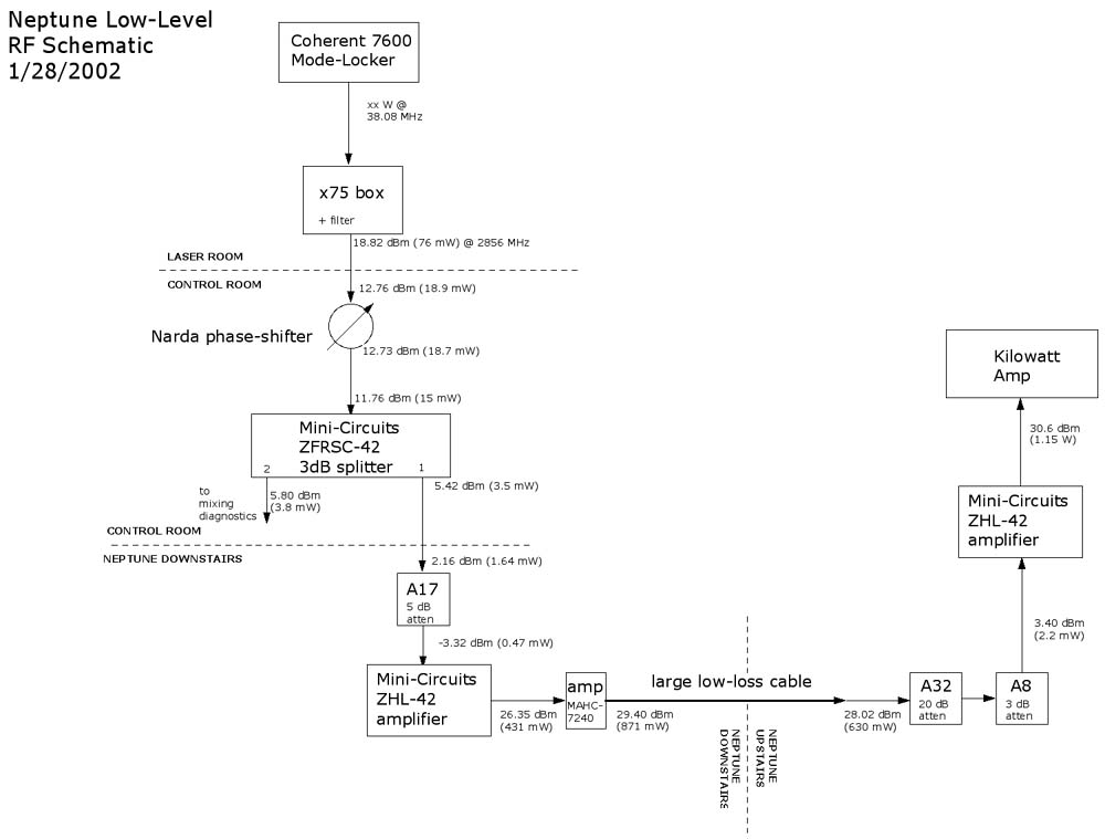
The ultimate source of RF power for Neptune is the Coherent 7600 mode-locker in the laser room. This unit produces roughly ?? watts of continuous power at 38.08 MHz, which is synchronized to the laser pulse [at nanosecond scales] by feedback stabilization. (see Timing documentation.) The output from this is frequency-multiplied by 75 to give 2.856 GHz, using the so-called "x75 box" located in the laser room behind the mode-locker. This "low-level RF" signal leaves the laser room on a semi-rigid cable (for minimal power losses) on its way to the klystron area.
1.2 Amplification and Transmission of Low-Level RF
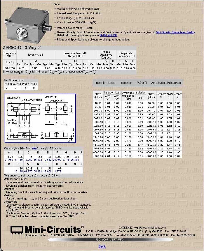
Currently (Jan. 2002) the entire low-level signal is brought into the control room, where it is divided using a mini-circuit 3-dB splitter unit (MiniCircuits model ZFRSC-42). Half the power can then be used for RF phase diagnostics by mixing it with loop signals from the PWT linac or electron gun [see diagnostics]. The remaining half is the source of the high-power RF; the phase of this signal (and hence the timing of the laser pulse relative to the phase of the klystron RF) is controlled by a manual phase shifter in the control room. This shifter has a dial readout which is calibrated in degrees per gigacycle; hence one unit represents roughly 3 degrees of phase at the operating frequency of 2.8 GHz.
Phase shifter. Readout on left; input port upper left corner, output lower left corner.
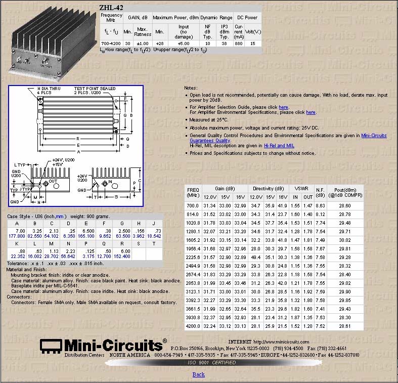
After phase shifting, the remaining low-level power is amplified (a mini-circuit amplifier, model ZHL-42, with 30 dB gain is mounted on top of the rack housing the magnet power supplies; there is an additional 3 dB added afterward), transmitted upstairs on low-loss accordion cable, attenuated, and amplified again (another ZHL-42 on the upstairs control rack) before being fed to the kilowatt amplifier. This seemingly illogical mixture of amplification and attenuation is designed to produce roughly 1 watt of power, which is the required input level for the kilowatt amplifier, while accounting for cable losses and the fixed gain of available RF amplifiers. The components are diagrammed in detail, and measured RF levels noted, on this figure.
A commercial high-power microwave amplifier, the "kilowatt amp", is used to generate the input RF for the klystron. The unit, a Pro-Comm model PC1000A1, is a pulsed device; with input of xx W c.w., it produces an output pulse of xx W for xx µs when triggered with a . signal. [see specs] During normal operation, this trigger signal originates from the master trigger box in the control room and is transmitted upstairs on fiber-optic cable to prevent ground-loop interference from the MARS laser during the beat-wave acceleration experiment. (See the Timing document for more details.)
1.3
Klystron Operation and Output (High-Level RF, Part 1)
A klystron is, fundamentally, an RF amplifier. The PBPL has
used a variety of klystrons, but the principle of operation is
identical. About 1 kW of pulsed RF power at 2.856 GHz is fed
into the klystron tube from the kilowatt amp; at the same time,
a high-current, high-voltage pulse is received at a transformer
and used to create and accelerate a spiraling electron beam in
the base of the klystron. The beam couples to the input RF and
gains energy in a series of cavities as it moves vertically up
the klystron, then radiates strongly into an output cavity and,
finally, is dumped into a resistive load. The output cavity radiation,
generally tens of megawatts at the same 2.856 GHz frequency, is
in a pulse several microseconds long. A rectangular waveguide
output feed carries the radiation into the lab.
The current (01/2001) klystron, a xxx model xxx, produces up to about 18 MW of RF in a flat-topped pulse 3 µs long. The cylindrical base of the klystron contains the pulse transformer, which is submerged in oil for insulation; the high-current cable transmitting the modulator pulse is attached here. The actual klystron tube is mostly invisible, since it sits inside a permanent-magnet housing. The input power must be supplied to the bottom end of the tube; thus the kilowatt-amp signal travels on a high-power coax cable which reaches the klystron and then runs down inside the magnet housing. At the upper end, most of the visible structure is actually the beam dump.
There are three requirements for correct operation of the klystron:
1.4
High-Level RF Distribution
RF power is distributed from the klystron to the gun and PWT
linac via WR-284 copper waveguide. The system (diagrammed in
Figure xx) incorporates phase and attenuation controls as well
as diagnostics. Windows immediately before the gun and linac,
as well as the one at the klystron, isolate the high vacuum in
the beamline from the gas-filled waveguide. .. Windows are chinese
made.
The waveguide system is filled with sulfur hexafluoride (SF6), an inert, heavy gas which inhibits RF breakdown by resisting ionization. Neptune traditionally operates at a gauge pressure (i.e. above atmospheric) of 28 psi within the waveguide, as measured on a pressure transducer placed before the linac window. This is a compromise value, balancing the anti-breakdown effects of high gas pressure with an acceptable level of pressure (28 psig + 15 psi [1 atm]) on the windows. One quick way to check for window leaks is to increase the gas pressure and watch for an effect on the ion pumps connected to the gun and linac.
To fill the waveguide with SF6, use the port on the upper side of the isolator, just after the klystron. The system tends to leak, probably through that same isolator port, at a slow rate (roughly 0.07 psi/day); consequently, the pressure must be checked and brought back to 28 psi before every run. A tank of SF6 is kept near the isolator; to fill the system, connect the attached delivery line to the port on top of the isolator, then open the bottle, regulator, and needle valve on the line. Flow begins when the needle valve on the isolator fitting is opened. There is a pressure gauge on the isolator, but it is more accurate to use the pressure transducer near the linac. This signal is read in the control room using the LabView vi readpressure (see figure xx); hence, someone must be in the control room to monitor the pressure and give a signal when 28 psi is reached. When filling is completed, close all valves and disconnect the bottle.
how does the transducer work?
Flanges: standard kinds, specs
1.5 Components
Isolator: The isolator's function is to protect the klystron from reflected RF power returning from elsewhere in the system. The unit in Neptune was manufactured by Titan-Beta; the specifications are given in xxxxxxxx
Splitter: Once it has arrived in the bunker, power is split between the linac and gun in a 4.7-dB hybrid splitter, meaning that the power ratio between linac and gun is 2:1.
Gun Attenuator: The power attenuator before the gun works on the principle of phase cancellation. (There is no direct phase control of the gun; we control overall phase and linac-to-gun phase.) Power is split evenly between two arms, one of which is of variable length; when the two signals are recombined, interference reduces the overall amplitude. (Maximum rejection is said to be about 20 dB.) The variable-length portion of the interferometer is a plunger-and-bellows system, so that a shaft is rotated by a stepper motor to control the path length. The motor is controlled by a switch in the control room, right-hand rack, with a digital readout on the panel above. The amount of attenuation produced is a nonlinear function of the plunger position, so if a particular power is required one must use the scope waveforms to set it correctly. (To order-of-magnitude level, 1 dB of attenuation is equivalent to about 20 units on the display.) Since the motor is geared onto the shaft by a set screw, which can be easily stripped if the motor attempts to move the shaft beyond the limits of its travel, the range limit of 0-180 (shown on the panel) must be observed. Usual set point: 141
Linac Attenuator/Shifter: The linac can be both attenuated and phase-shifted. The principle is the same as the gun attenuator (input power is split in half and sent to variable-length arms) but in this case both path lengths can be adjusted, allowing amplitude reduction and overall phase control relative to the gun. The same mechanical limitations apply (total range of the attenuator is 170-330, and of the phase shifter 50-350). The calibration of the attenuator is the same as for the gun; the phase shifter motor is calibrated to read out in degrees. Usual set point: Attenuator: 192, Phase: 170-175
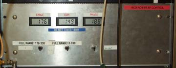
Phase control panel. The readouts and switches control (left to right): linac attenuation, gun attenuation, linac phase relative to gun.
1.6 Diagnostics
RF signals can be sampled at a number of locations in the
waveguide system using directional couplers, which measure traveling
power in a guide, and loops, which sample power levels in a cavity.
In both of these types of port, a very small portion of the RF
power is split off and can be fed to a detector or used for phase
measurements. An accurate power measurement, naturally, requires
knowledge of the coupling strength between the waveguide/cavity
and the diagnostic port. Such coupling is difficult to measure
well (specialized instrumentation is needed) and we generally
rely on manufacturers' specifications.
Directional couplers, sampling "forward" (toward
beamline) and "reverse" (reflected from beamline) power
levels, are installed:
(1) between kilowatt amplifier and klystron, called "KW amp
forward/reverse";
(2) after klystron and isolator, before the waveguide enters the
bunker, called "klystron forward/reverse";
(3) after splitter and attenuator, just before gun, called "gun
forward/reverse";
(4) after power splitter on linac side, but before attenuator,
called "linac forward/reverse 2";
(5) after power splitter and attenuator, just before linac, called
"linac forward/reverse".
Not all of these are equally useful or well calibrated. (2) in
particular has a poor location at which there tends to be a standing-wave
component in the waveguide. (4) is redundant and not normally
used.
There are cavity loops installed on the linac (in the last full cavity) and in the gun's full cell. These are ordinarily used for phase mixing, but can be used for power monitoring as well, although the calibration uncertainties are relatively high.
Known coupling factors (as traditionally used in the LabView "Power Read" vi's--see section 1.7) are as listed here:
| Port | Attenuation (dB) |
| Klystron Forward |
47.5
|
| Klystron Reverse |
47.5
|
| Gun Forward | 49 |
| Gun Reverse | 49 |
| Gun Loop | 63.5 |
| Gun half-cell | 45.8 |
| Linac Forward | 48 |
| Linac Reverse | 48 |
| Linac Loop | 49 |
| Kilowatt Amp Forward | 20.5 |
| Kilowatt Amp Reverse | 20.4 |
show/discuss typical waveforms from each of these locations
RF power levels are ordinarily measured by crystal detectors, which are essentially diodes that rectify the RF signal and produce a DC voltage output. The range of powers that can safely be measured using a crystal detector is limited; in Neptune input power levels are kept below about 15 mW, to avoid burning out the crystals. (One rule of thumb is that one should rarely see more than 100 mV of signal from any crystal.) Since there is usually much more power than this coming out of a given RF coupler, calibrated attenuators are used.
The relationship between output voltage and input RF power for a crystal is nonlinear, but can be reasonably well fitted to a quadratic, with constants dependent on the particular crystal in use. All the crystals installed in the lab have been calibrated using a sweep generator and power meter. Data for each labeled crystal can be found on the hard drive in the control room, and fitting constants are reproduced in this document (see Appendix, Attenuator and Crystal Calibrations). Once the calibration is known, the calculation of actual RF power levels is done automatically within LabView.
The detector signals are sent to the control room through low-loss RG-228 cable via a patch panel located under the beamline table at the gun end. The layout of both patch panels is given in a table elsewhere in this documentation. Signals from the control room patch panel can be observed on scopes and, if desired, be downloaded to computer using LabView. Typically this is done using the Tek TDS 3052 next to the control panel, which has GPIB address 10. That address is hard-wired into the Power Read vi [see below], so the vi must be changed if a different scope is to be used.
Phase information is obtained with RF mixers, three- or four-terminal devices which give a DC output proportional to the sine or cosine of the relative phase of two input signals. We have the ability to observe relative phases of low-level RF, gun, and linac; using the beam itself as a diagnostic it is also possible to measure phase of laser with respect to any of the above. A feedback stabilization circuit based on observing and correcting phase changes is under construction and will be added to this document when it is operational.
1.7
LabView Controls
RF power diagnostics in LabView use some variety of the "Power Read" vi. The most current version, which uses the correct parabolic fit for crystal calibrations, is called "Power Read TDS 3052 Parabola". In normal operation, scope traces of RF waveforms are downloaded via GPIB and calibrated automatically, so that they are displayed with units of watts on the vi front panel. The source of the signal must be selected in the control panel for each trace for correct calibration. (This vi also expects the waveforms to be displayed on the control-room TDS 3052 scope, with GPIB address = 10.) Set the control panels and press the "run" button; the program will download 2 traces and exit.
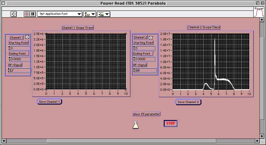
Correct calibration depends on accurate information in the parameter file associated with the vi. Running the vi with the front-panel switch up will bring up the CD and attenuator file, in which each port is associated with the correct detector and amount of attenuation. (See figure below.) These should be checked for accuracy before important RF measurements, since attenuators and CDs have a habit of migrating within the lab. To save any changes to the parameter file, one must first choose "Make current settings default" from the Operate menu within LabView, then save the vi.
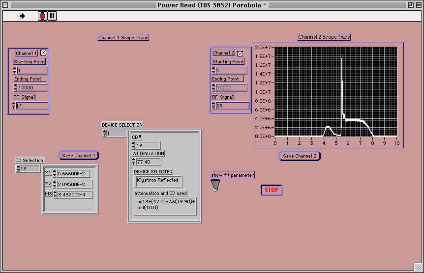
This figure shows the calibration file open within the vi. The left control panel shows the three calibration constants associated with a given crystal detector (CD). The right panel shows, independently, the CD number and total attenuation (port coupling + external attenuators) for each available waveform.
The calculation routine performed by the vi converts the digitized waveform (in volts), to millivolts; converts that value to milliwatts using the CD calibration; converts milliwatts to dBm; adds the attenuation value from the device selection panel; re-converts to milliwatts and finally to watts.
Appendix: Attenuator and Crystal Calibrations and Locations
Attenuator Calibration
(measured with RF generator and power meter)
|
Attenuator Label
|
Meas. atten @ 2856 MHz (dB)
|
| A1 | 20.54 |
| A3 | 20.31 |
| A4 | 20.43 |
| A6 | 20.01 |
| A8 | 2.93 |
| A9 | 20.33 |
| A10 | 20.25 |
| A11 | 13.69 |
| A13 | 9.91 |
| A14 | 9.95 |
| A17 | 5.48 |
| A18 | 2.50 |
| A19 | 30.21 |
| A21 | 30.17 |
| A28 | 20.21 |
| A31 | 9.71 |
| A32 | 20.32 |
| A38 | 30.24 |
| A39 | 46.04 |
Crystal Detector Calibration
(measured with RF generator, power meter, and voltmeter)
To obtain power reading, in milliwatts, as a function of voltage signal in millivolts, use parabolic fit to calibration curve, i.e. P[mW] = m1 + m2V + m3V 2.
| Detector | m1 | m2 | m3 |
| CD-1 | 7.1065 x 10⁻¹ | -1.1461 x 10⁻² | 1.4029 x 10⁻³ |
| CD-2 | 4.3662 x 10⁻² | 1.6627 x 10⁻³ | 1.16 x 10⁻⁵ |
| CD-7 | 4.2809 x 10⁻¹ | 3.4368 x 10⁻³ | 8.2053 x 10⁻⁴ |
| CD-13 |
5.666 x 10⁻²
|
2.095 x 10⁻² | 3.432 x 10⁻⁴ |
| CD-14 | 1.389 x 10⁻¹ | 1.748 x 10⁻² | 3.029 x 10⁻⁴ |
| CD-15 | 5.97 x 10⁻² | 2.125 x 10⁻² | 3.502 x 10⁻⁴ |
| CD-16 | 1.2744 x 10⁻² | 4.4756 x 10⁻⁴ | 2.9114 x 10⁻⁶ |
| CD-18 | 2.1178 x 10⁻² | 7.4898 x 10⁻⁴ | 4.9079 x 10⁻⁶ |
| CD-19 | 1.4995 x 10⁻² | 5.4087 x 10⁻⁴ | 3.6242 x 10⁻⁶ |
| CD-21 | 1.3792 x 10⁻² | 4.5703 x 10⁻⁴ | 2.8098 x 10⁻⁴ |
| CD-22 | 1.628 x 10⁻¹ | 2.6165 x 10⁻² | 5.1408 x 10⁻⁴ |
| S/N 192453 | 4.3855 x 10⁻¹ | 1.3553 x 10⁻² | 2.5176 x 10⁻³ |
| S/N 192454 | 4.1143 x 10⁻¹ | 1.3573 x 10⁻² | 1.8205 x 10⁻³ |
| S/N 192455 | 4.2077 x 10⁻¹ | 1.687 x 10⁻² | 2.4577 x 10⁻³ |
| S/N 192456 | 2.9451 x 10⁻¹ | 2.1619 x 10⁻² | 1.969 x 10⁻³ |
Crystal Locations
| Name | Detector | Attenuators | Total atten. for this port |
| KW amp F | CD-14 | A3 (20 dB) | 40.8 dB |
| KW amp R | none | 20.4 dB | |
| Klys F | CD-16 | A39 (44 dB) | 93.5 dB |
| Klys R | CD-13 | ||
| Gun F | CD-21 | A6 (20) + A1 (20) | 89.5 dB |
| Gun R | CD-15 | A28 (20) + A9 (20) | 89.5 dB |
| Gun loop | CD-19 | A4 (20) + A13 (10) | 93.8 dB |
| Linac F2 | none | A25 (20) + A2 (20) | |
| Linac R2 | none | A5 (20) + A27 (20) | |
| Linac F | CD-18 | A18 (2) + A20 (30) | 48 dB |
| Linac R | CD-2 | A31 (11) + A19 (30) | 87.9 dB |
| Linac loop | none | A11 (14) + A14 (10) | 72.6 dB |