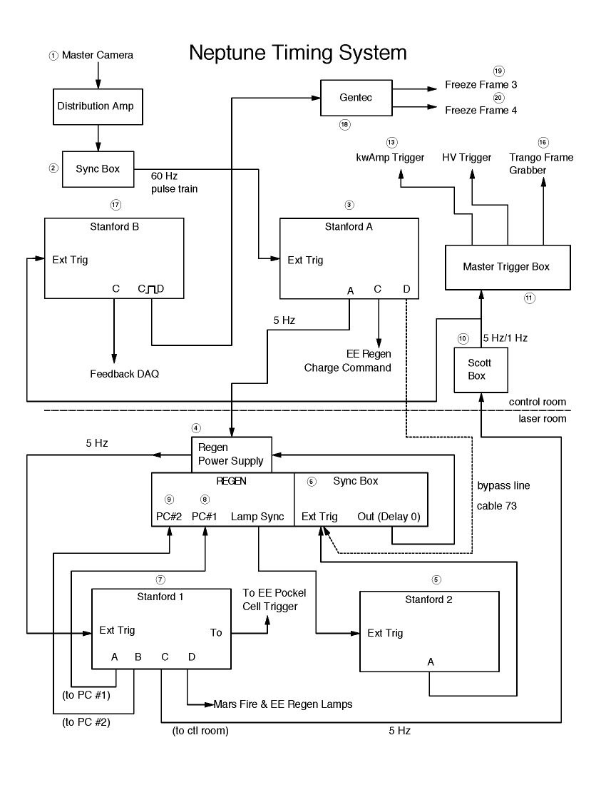
Trigger System Block Diagram. Click image for enlarged view.
This document describes the details of the timing and triggers for Neptune components, and is meant to be read in conjunction with a block diagram showing the entire timing chart. Numbers on the diagram correspond to those below.
Trigger System Block Diagram. Click image for enlarged view.
1. Master Camera: The ultimate clock reference for the system. The master camera is a Cohu CCD located in a homemade aluminum box, under the console on the right in the control room; there are connectors on the box for power in and video out. The video signal from the camera passes through a distribution amplifier (located on top of the camera box) and then to the linefinder. The camera also happens to be imaging a digital clock, which can be observed on the video monitors on channel 16.
2. Linefinder: Visual Information Institute model VII-11. Video signal from master camera connected to DISPLAY VIDEO, output at SCOPE SYNC. Front panel display is set to 0000. The linefinder locks onto the 60 Hz frequency at which the video frames are received and outputs a 60 Hz pulse train to Stanford A.
3. Stanford Box A: Stanford Research model DG535 4-channel digital delay generator. Located in the control room under the console on the left. The 60 Hz pulse train from the linefinder is the EXT TRIG input; output A is the only one used by the photoinjector. The box does not add delay, but outputs a 5 Hz pulse train (10 ms pulses) which is usable for precise triggering and is sync’d to the master clock; this pulse train is sent to the laser room. Output C is used to trigger the regen of the Mars laser when synched.
Trig = External, +1.00 V, rising edge, Hi Z
Ch A = T + 0.00, 50 ohms, TTL, inverted (to regen power supply)
Ch C = A + 17 ms, Hi Z, TTL, normal (to EE regen)
4. Regen Power Supply: The control and power box for the regen amplifier in the laser room. The pulse train from Stanford A is on a white BNC marked “5 Hz Trigger” which drops down from the cable tray above the regen and connects to a 4-wire control cable through a homemade adapter; the other two control wires are held at 5 volts DC. Each pulse from the Stanford is received as a “charge” command by the flashlamps of the regen, and the 5 V signal is connected to the “fire” command, meaning that the lamps fire as soon as they are fully charged, which takes 80 ms. The input cable with the charge and fire signals connects to the OSC EXT input on the back of the power supply, under the optical bench. A trigger signal (inverted, 3.5 V, about 400 ns) is produced when the lamps fire, which is sent to Stanford 2 from the LAMP SYNC connector on the regen front panel.
5. Stanford Box 2: Stanford Research model DG535 4-channel digital delay generator, also known to the engineers as Stanford C. Located in the laser room, above the optical bench, on the right. The lamp sync trigger from the regen power supply (4) is the EXT TRIG input. Output A (the only one in use) has delay set to about 70 µs and is sent to the regen/RF synchronization box, part of the regen control panel. For e-beam purposes, this Stanford box is redundant with Stanford 1; historically, the delay of 70 µs was used as a fine adjustment for the long (669µs) flashlamp wait time on Stanford 1.
Ch A = T + 70µs, Hi Z, Var, 1.5V (to regen synch box)
(Saved setting #5)
NOTE: If running RF only (no laser), this Stanford box is used as the master trigger. To do this, use saved setting #9, which changes the trigger to "line" from external, and connect output B (delay = 0.0) to the input of Stanford 1, in place of the RF sync signal. These instructions are posted on the regen box.
6. Regen/RF Synchronization Box: Part of the regen control panel on the side of the unit. Here, the delayed firing signal from Stanford 2 is synchronized at the ??? level with the RF signal (at 38.08 MHz) taken from the mode-locker. In effect, the 5 Hz pulses from the lamp firing are delayed until a zero-crossing of the RF is observed. The signal from Stanford 2 is the EXT TRIG input; the mode-locker connects to RF IN, and output (still at 5 Hz) is taken from DELAY0 and sent to Stanford 1.
7. Stanford Box 1: Stanford Research model DG535 4-channel digital delay generator, known to the engineers as Stanford D. Located in the laser room, above the optical bench, on the left. The EXT TRIG input is the synchronized 5 Hz pulse train from (6), and all four outputs are used. Output A is sent to the first Pockels cell (8) of the regen cavity (connector PC#1 on regen control); this delay of 0.7 ms waits for the lamp discharge to peak before allowing laser light into the regen cavity. Output B (delay = 250 ns) triggers the second Pockels cell (9) of the cavity (connector PC#2) to eject the amplified laser pulse. Since the cavity roundtrip time is 7 ns, this gives 35 passes through the regen. Output C (delay = B–9.2 µs) is sent to the control room, where it is used to trigger the linac/gun RF systems. The negative delay is required by the extra time needed to fire the klystron modulator. Output D is the regen 'fire' pulse for the Mars laser.
T0 = T +85 ns (fixed), 50 ohms, TTL, normal (to ext trigger for EE Stanford 1 when synched)
Ch A = T + 669.105740 µs, Hi Z, Var, 1.5V (fire Pockels cell 1)
Ch B = A + 253 ns, Hi Z, Var, 1.5 V (fire Pockels cell 2)
Ch C = B - 9.2 µs, Hi Z, TTL, normal (to Scott box and high-voltage triggers)
Ch D = T + 73.6 µs, 50 ohm, TTL, normal ("fire" command, Mars laser RGA, when synched)
Ch AB-bar: Hi Z, TTL, normal (to EE frame-store trigger)
8. Pockels Cell 1: Fires to allow laser light into the regen cavity. Triggered from output A on Stanford 1.
9. Pockels Cell 2: Fires to eject an amplified laser pulse from the regen cavity. Triggered from output B on Stanford 1.
10. 5:1 Frequency Divider: Homemade black box under the console (on left side) in the control room, otherwise known as the “Scott box”. The 5 Hz pulse train from Stanford 1, output C, is the input, and the output is every fifth pulse, i.e. a 1 Hz pulse train. The division by five is necessary because the laser system is designed to run at 5 Hz but the linac overheats unless run at 1 Hz. There are two connectors and a mode switch, which is down for frequency division (up = 5 Hz output). Left connector is input, right is output, which is split between the main trigger panel and Stanford B.
11. Trigger Panel: The main trigger box in the control room, on the right hand rack, near the top. Receives master trigger from the Scott box at MASTER IN connection; trigger signals at 4 V are sent to all other synchronized systems in the photoinjector, including RF and diagnostics. Further delays are included for many of these signals; these delays can be adjusted using the small potentiometer screws on the front panel. (The upper screw adjusts delay and the lower adjusts the pulse length; different ranges are available on the different outputs, so check with scope.) Measured delay and width values (12/01) are:
"HV" trigger: 4.4 µs delay, 3.5 µs width
"KW amp" trigger: 2.4 µs delay, 9.2 µs width
"ICT gate" trigger: 96 ns delay, 26 µs width
"Video" trigger: 21 µs delay, 1.88 ms width (inverted-- sits high, triggers low)
The second rank of connectors (to the right of the IN connection) are triggered from the SECONDARY INPUT connector on the far right. Normally the signal from the Scott box is split and sent to both inputs. There are three 4V outputs and a small-amplitude (about 400 mV) output, labeled as such. The unlabeled output has an extra-long delay range (greater than 10 ms). These are used for miscellaneous scope and video triggers, especially when running in synch with the Mars laser.
12. EE Optical Converter 3: Receives trigger from KW AMP output of trigger panel, converts to fiber optic pulse which is transmitted to (13). On the engineering console in the control room; has an old label reading “LINAC”.
13. Kilowatt Amplifier: Pro-Comm RF amplifier, model PC-1000A1. Optical pulse from (12) is converted to analog signal and received at PULSE INPUT terminal. RF power goes to klystron from here.
14. EE Optical Converter 2: Receives trigger from HV TRIGGER output of trigger panel, converts to fiber optic pulse which is transmitted to (15). On the engineering console in the control room; has an old label reading “EBEAM”.
15. Thyratron Trigger: SCR thyratron driver, model 730-788. Optical pulse from (14) is converted to analog signal (in small box) and received at J4 (TRIGGER INPUT) terminal on back panel. Output is a high-voltage pulse which triggers the thyratron, in turn firing the klystron modulator.
16. Frame Grabber: Board installed in the control computer (“Durandal”). The VIDEO OUT signal from the trigger panel is received at a BNC connector on the back of the computer.
17. Stanford Box B: Stanford Research model DG535 4-channel digital delay generator. Located in the control room, under the console, on the right. The EXT TRIG input is from the Scott box. At least five outputs are used. The T0 fixed-delay output triggers the gate generator for the RF mixer phase ADC. Output B is currently unused, but is available for e.g. externally triggering scopes. Output C is used to trigger the Marcellus DAQ board for phase data acquisition. The combined signal CD (which is high between triggers C and D) is used by the engineering system (goes to the BNC box for video triggers), and CD-bar (inversion of CD) triggers the frame grabbers for beamline video (sent to the IN terminal on (18)). Output AB-bar gates and triggers the ICT via the control room patch panel.
T0 = T +85 ns (fixed), Hi Z, TTL, normal (to ADC gate generator for phase signals)
Ch A = T + 9.07 µs
Ch B = A + 30 ns
Ch C = T + 0.00, Hi Z, TTL, normal (to Marcellus DAQ board for phase readout)
Ch D = C + 28 ms
Ch AB-bar: 50 ohm, NIM (to LeCroy ADC for ICT signal, via patch panel)
Ch CD: Hi Z, TTL, normal (to engineers' BNC video trigger box)
Ch CD-bar: Hi Z, TTL, normal (to power distribution amplifier)
(Settings saved in #9.)
18. Power Distribution Amplifier: Distributes video signal to the two freeze-frame units.
19. Freeze Frame #1: Left ? side of console; receives trigger signal from (18) on ??
20. Freeze Frame #2: Right? side of console; receives trigger signal from (18) on ??.
21. Control Room Patch Panel: On left rack in control room. Input signal from channel AB-bar of Stanford B arrives at "ICT gate" front-panel connector and is sent into bunker on channel 22 (cable is SIG11).
22. Bunker Patch Panel: Located on the south (short) end of the table, under the gun. ICT gate trigger on channel 22.
23. ICT Reader: LeCroy model 2250L ADC module in the crate under the ICT, in the bunker. Receives the trigger pulse from Stanford B via patch panels at GATE input, and sends reading from ICT back to control room (see Diagnostics).
24. Gate Generator: LeCroy model 2323A gate and delay generator, in crate on right-hand rack in control room. Receives trigger from T0 of Stanford B at START connector; produces gate signal which is the integration window used by the RF phase reader ADC. Output is at DLY connector; gate timing is set using the DELAY WIDTH knob and is currently set to 30 ns.
25. Mode Locker: Coherent model 7600 mode locker, part of the Antares laser system. Responsible for picosecond-level stabilization of laser and RF. Produces microwave output at 38.08 MHz which is fed to the regen/RF synchro box, the timing stabilizer, and the RF system. Should never be turned off.
26. Timing Stabilizer: Lightwave model 1000. Input from a fast photodiode in the laser which reads the phase of laser light; signal is mixed with RF from the mode locker and fed back to the mode locker again.
27. Antares Laser: Receives RF from mode locker, photodiode feedback using timing stabilizer.
28. X75 Box: Hardware mounted behind mode locker above optical bench. Frequency multiplies the 38.08 MHz RF signal from the mode locker (25) by 75 to make 2.856 GHz. This low-level signal is the RF input to the kilowatt amplifier.
29. Phase Reader ADC: LeCroy model 2250 ADC, in crate on right-hand rack in control room. Acquires and digitizes the output levels from phase mixing, used to generate phase values for RF feedback. Triggered by LeCroy gate generator in the same rack (at GATE input); values are sent to Marcellus (see Diagnostics).
29. Marcellus DAQ board: Model xxx National Instruments digital/analog I/O board, connected to Marcellus. Triggered at the EXTTRIG input from Output C of Stanford B; used to acquire RF phase information and control phase shifters for RF feedback stabilization.