This document describes the operation and control of all components of the photoinjector beamline: electron gun, accelerator structure, all steering and focusing magnets, and chicane compressor. (Diagnostics, such as phosphor screens, ICT, and BPMs, are described in a separate document, as are water and vacuum systems.)
Contents:
The Neptune photoinjector beamline's function is to deliver precisely controlled, high-charge, low-emittance, ultrashort electron bunches to experiments located at any point along the beam path. Beam parameters can be varied, but in normal operation the beam has energy of roughly 11.5 MeV, bunch length 4 ps, and emittance 8 &Mac185; mm mrad, with a charge per bunch between 100 and 300 pC.
Beamline elements consist of the gun and RF accelerator (linac), 10 quadrupole magnets, one solenoid magnet, 10 steering magnets, and a chicane compressor/dipole. Starting from the laser photocathode on the electron gun, the beam passes first through an emittance-compensating solenoid and is accelerated to its final energy in the linac. At this point the beam is focused by a quadrupole triplet into the chicane compressor. The chicane may be energized or not; if the magnets are on, the beam is bunched; if not, it is unaffected. The final chicane magnet may also be used as a dipole for steering to a spectrometer and beam dump. Following the chicane, two more quad triplets transport the beam through a 'folding box', where a co-propagating laser beam can be injected, and focus it at a specific target location. Finally, there is a high-dispersion spectrometer and beamdump. The total beamline length is about 6.7 meters.
This figure shows a schematic drawing of the beamline.
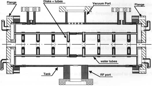
This RF linac (specifically, a plane-wave transformer or PWT) accelerates the beam from roughly 4 MeV to roughly 11 MeV over 42 cm. It is a washer-loaded cylindrical cavity, with 7 full cells and 2 half-cells separated by irises which are supported on longitudinal cooling tubes and separated from the cylinder wall. RF power is coupled in through the center cavity, and 4 water lines pass through the irises and are used for temperature stabilization. An RF antenna (the "linac loop") is installed on a side port.
Longitudinal cross-section of the PWT linac. The beam axis is the centerline of the drawing. The irises or disks, seen in cross-section, are supported by the water tubes from each end cap as shown. There are actually four water tubes, equally spaced in azimuthal angle. Within each end cap is a water reservoir. The entire structure is constructed in two halves which were then fitted together in the center and brazed; each half has a separate water supply. (Drawing from R. Zhang's thesis.)
This PWT, the so-called Mark III, was built at SLAC and UCLA in the early 1990s. As an RF structure, a PWT is unusual in that the cell-to-cell coupling is extremely strong and almost independent of the operating conditions. Unlike conventional linacs, it operates in a TEM-like hybrid mode in the coaxial region outside the irises, so that the fields there are similar to those of a plane wave in free space and propagate at the speed of light; meanwhile, each individual cell supports a longitudinal electric field. The structure is designed to resonate at 2856 MHz, with detailed tuning accomplished by changing the temperature of the water, which affects mostly the longitudinal dimension of the cells. The tuning coefficient is about 50 kHz per degree C. The outer wall has no direct temperature control, though it is cooled slightly by a water manifold which compensates for RF heating during operation. Calculations and experience have shown that the resonance frequency and fields are relatively insensitive to the outer wall temperature. (See below for practical information on operating the PWT.)
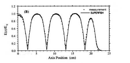
This figure shows the field profile on axis, as measured during construction by R. Zhang, for half of the tube, starting from the center.
Controlling the phase and amplitude of RF power injected into the PWT is accomplished via the attenuator/phase shifter on the input waveguide. See the RF Systems document for details.
How to run the PWT.
The solenoid is actually a set of two electromagnetic windings located side by side and concentric with the beam pipe. Each can produce an axial field which will focus the beam coming off the gun cathode. In current operation, only the upstream winding is energized. Each winding is water-cooled via a six-channel manifold, but only the upstream manifold is currently connected to the water supply. The power supply is not interlocked with the water flow, so operators must be careful to turn on water before running the magnet.
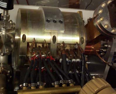
The solenoid in place. The gun is on the right side, upstream of the solenoid. The two water manifolds are visible, as well as current leads connected on the right (upstream) coil.
Field: One winding consists of 84 turns. Using a POISSON model for the magnet, we have a working calibration for the peak axial field of 10.6 gauss/amp. Normal operation, which gives the correct field for emittance compensation of the beam, is at a current near 190 A (i.e. peak field of 2.0 kG). The POISSON inputdeck for the solenoid is available here.
This figure shows a plot of the calculated field shape (from POISSON) for a current of 30000 ampere-turns; z=0 at the gun cathode. There is no bucking coil at Neptune.

Control: The winding in use is powered by an EMI power supply, model TCR20T250, which can produce up to 250 A at 20V. The supply is controlled by a 0-5V DC signal applied to terminals on the back panel. (5V represents full voltage output, i.e. 20V.) This signal is generated from Durandal, on channel DAC0 of the MIO data in/out board (Board ID# 2), with the voltage level controlled within the Master Control vi.
At present the supply is voltage-controlled; the vi is calibrated to give the correct currents given the known solenoid resistance (roughly 6 milliohms). The current meter on the supply does not work. Both current control and current readback have been attempted in the past; one of these should eventually be implemented.
Connection modes for the power supply:
For remote control of output voltage, connect jumpers on rear terminal strip as shown, and apply control voltage of 0-5 V between terminals 4 and 6. Front panel control is disabled.
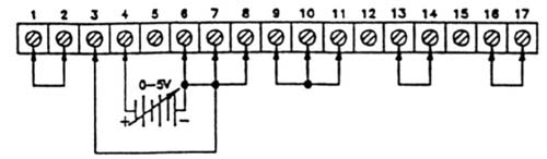
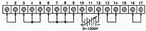
For remote control of output current, connect jumpers on rear terminal strip as shown, and apply control voltage of 0-100 mV between terminals 10 and 12. Front panel control is disabled.
Appendix: List of CAMAC modules and channels
Control Room Crate: GPIB = 16
N=3: Degaussing Supply Relays
(Normally open; switches magnets between main supply and degaussing supply)
Joerger ddd
| Relay | Function (when closed) |
| 1 | Degauss supply connected to Quad A1 |
| 2 | Degauss supply connected to Quad A2 |
| 3 | Degauss supply connected to Quad A3 |
| 4 | Degauss supply connected to Quad A4 |
| 5 | Degauss supply connected to Quad A5 |
| 6 | Degauss supply connected to Quad A6 |
| 7 | Degauss supply connected to Quad A7 |
| 8 | Degauss supply connected to Quad A8 |
| 9 | Degauss supply connected to Quad A9 |
| 10 | Degauss supply connected to Quad A10 |
| 11 | |
| 12 | Degauss supply connected to Chicane |
| 13 | |
| 14 | |
| 15 | |
| 16 |
N=5: Chicane Switch Box relays (Normally open)
Joerger ddd
| Relay | Function |
| 1 | |
| 2 | Open = chicane mode, closed = dipole mode |
| 3 | |
| 4 | |
| 5 | |
| 6 | |
| 7 | |
| 8 | |
| 9 | Polarity switch, trim coil 2 (open = + current) |
| 10 | Polarity switch, trim coil 3 (open = + current) |
| 11 | Polarity switch, trim coil 1 (open = + current) |
| 12 | Polarity switch, trim coil 4 (open = + current) |
| 13 | Degauss current to coil 3 only |
| 14 | Degauss current to coil 2 only |
| 15 | Degauss current to coil 4 only |
| 16 | Degauss current to coil 1 only |
N=6: DAC output for quad control
Joerger ddd
| Channel (A) | Connected to: |
| 0 | Quad A8 |
| 1 | Quad A9 |
| 2 | Quad A10 |
| 3 | |
| 4 | |
| 5 | |
| 6 | |
| 7 | |
| 8 | |
| 9 | |
| 10 | |
| 11 | |
| 12 | |
| 13 | |
| 14 | |
| 15 |
N=10: DAC output for quad/chicane control
Joerger ddd
| Channel (A) | Connected to: |
| 0 | Quad A1 |
| 1 | Quad A2 |
| 2 | Quad A3 |
| 3 | Quad A4 |
| 4 | Quad A5 |
| 5 | Quad A6 |
| 6 | Quad A7 |
| 7 | |
| 8 | |
| 9 | |
| 10 | Chicane trim coil 1 |
| 11 | Chicane trim coil 2 |
| 12 | Degaussing supply |
| 13 | Main chicane supply |
| 14 | Chicane trim coil 3 |
| 15 | Chicane trim coil 4 |