Klystron (Dis-)Assembly at Neptune
or, Everything You Wanted to Know About How to Take Apart a Klystron
This note is intended to summarize knowledge gained from long and tedious experience with placing klystron tubes in operation: correct mounting of the tube within magnet and pulse transformer tank, and connection to the waveguide system. Klystron unmounting is required when the tube is to be removed, of course, but also to gain access to the magnet or pulse transformer tank for troubleshooting. This note is specific to Neptune because it assumes the availability of a crane.
Introduction: Orientation to Klystrons
The S-band klystron is used by both UCLA labs to amplify microwave pulses at a frequency of 2.856 GHz for high-power output. Achievable peak power levels are of order 20 MW in a 2.5 microsecond pulse, and typical duty cycle is 1 pulse per second, although the klystrons are rated for much higher average power. For more on operating specifications, see the main klystron page.
The klystron tube consists of an electron gun and a series of RF cavities, all under vacuum seal. The electron gun produces a high-current, low-energy beam that propagates upward. Several hundred watts of RF power is coupled into the first cavity from an external source, which causes the electron beam to bunch axially at the drive frequency. This bunching is enhanced in two more cavities, and the beam then radiates strongly into an output cavity before being dumped into a collector at the top of the tube. A waveguide attached to this output cavity carries the RF power away; at the exit from the tube, a microwave window protects the tube vacuum.
In order to operate, the tube needs a source of voltage and current for the electron gun and magnetic focusing for the propagating electron beam. To obtain a high-voltage pulse, we use a pulse-forming network of ten capacitors. Generally the voltage levels available from capacitor banks are on the order of tens of kilovolts rather than the 200 kV or more needed for tube operation, so the tube cathode is connected to a step-up transformer, located in the tank at the base of the assembly. The transformer is immersed in an oil bath for electrical insulation between the primary and secondary windings.
Magnetic focusing is provided by a toroidal permanent magnet which fits tightly around the tube and above the tank. Strong fringing fields of several hundred gauss or more are present, especially near its top and bottom, so one must be particularly careful with large steel objects that can crush a hand against the magnet (and which will also be very difficult to unstick).
| See this illustration! |
|
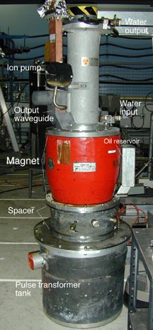 |
In this picture, the focusing magnet is painted red. The only visible portion of the tube itself is the beam collector emerging from the top of the magnet, with the output waveguide exiting just at the upper magnet pole inside a lead housing.
Cooling water ports are provided for cooling the gun and collecter.
Lead shielding is in place on top of the tube as well as in a collar surrounding the output waveguide and magnet upper pole. Additional thin sheets of lead surround the transformer tank and spacer above it.
The ion pump may not be present on all klystrons.
|
|
|
A. Dismounting a Klystron.
Rule 1: DON'T DO THIS UNLESS YOU MUST. If everything is working, there is no reason to open the tank. By doing so, you run the risk of damaging connections, making mistakes, and (most problematic) allowing debris to fall into the transformer oil, where it could interfere with and/or short out high-voltage connections.
Steps for disassembling klystron tube, magnet, and transformer tank:
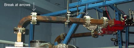
- If the waveguide is not already disassembled, vent the sulfur hexafluoride and break the seals, generally at either end of the long horizontal waveguide above the klystron. This piece can then be removed.
- Remove and drain water lines. Make sure flow is turned off, then undo and remove top (water outflow) line with a container below to catch spill. Repeat with lower (water inflow) line, which will contain more water.
- Turn off and disconnect ion pump, if there is one.
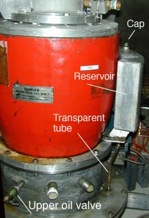
- Open the cap on top of the oil reservoir, and ascertain the oil level in the transformer tank and reservoir. The idea is to make sure the oil level is well below the magnet flange so it doesn't spill when you open. Often, the oil meniscus will be visible in the clear plastic tube connecting the tank to the reservoir. If not, you need to find out if the tube is full or empty. The quickest way to do this is to open the upper oil valve (with a bucket ready, of course) and check the head pressure. Basically, if you get a lot of flow there is oil in the reservoir, which should shortly drain, revealing the meniscus in the overflow tube. Keep draining until the meniscus is at least a couple of inches below the flange. If you get no or little flow, it's already empty and you're done.
- Remove the 12 bolts around the base of the magnet, as well as the oil reservoir (leave the tube in place). The reservoir will be dripping oil, so put it somewhere sensible.
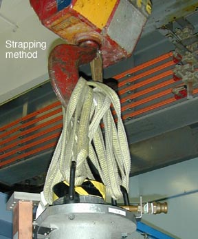
- If the waveguide bend is still attached, bolt four eyebolts to the top klystron flange, and attach 4 yellow nylon straps, each double thickness as shown below. Put these carefully on the crane hoist in a way that keeps the klystron level. NOTE: The orange ring with 4 hooks is TOO LONG to get the klystron out of the tank. (If the bend is removed, you can use three eyebolts, one opposite the waveguide.)

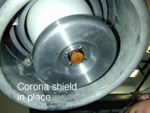
- Lift slowly in small stages, allowing oil to drain from the cathode assembly and corona shield as you go.
- If you are taking the tube out of the magnet as well, you should remove the corona shield from the end of the tube. We have two different styles of shield: a brass one which must be unbolted, and an aluminum one which is spring-loaded and snaps off. Photos show the second kind.

- Prepare a support stand for the tube and magnet. This will probably be two metal beams that are supported somehow from below. You want to rest the lower magnet flange on these supports, with the tube between them. The distance from the lower side of the magnet flange to the cathode tip is just under 12 inches, so you should have that much height (plus safety margin) in your support stand. The stand should also be lined with plastic to catch oil drips. See below:

- Move the tube with the crane, using a plastic garbage bag over the end of the tube to catch oil drips while moving across the floor. Set the magnet and tube down on the stand. If you just need access to the transformer tank, you can stop here.
- Now you can remove the bolts on the upper magnet flange (plus lead collar) to remove the tube from the magnet.
B. Mounting a Klystron.
This part deals with putting a klystron tube into a magnet and pulse transformer (considered to be separate). We start from the magnet sitting on the support stand described in Part A number 9, and the tube ready for lifting.
- Lift the tube on the crane for insertion into the magnet. If a waveguide bend is still attached, bolt four eyebolts to the top klystron flange, and attach 4 yellow nylon straps, each double thickness as shown below. Put these carefully on the crane hoist in a way that keeps the klystron level. NOTE: The orange ring with 4 hooks is TOO LONG to put the klystron into the tank. (If the bend is removed, you can use three eyebolts, one opposite the waveguide.)
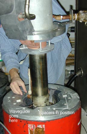
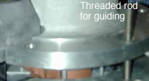
- Position the tube as exactly as possible over the magnet bore and lower slowly into place. If spacers are needed between the tube and magnet, insert them now. Adjust the crane carefully as you go, since the tube is not likely to hang exactly straight (center of mass is off-axis). In the last stages, it is helpful to insert threaded rods through the boltholes to guide the tube to the final position. The tube will likely seat 1/4 to 1/2 inch above the final position, when it begins to compress the O-ring at the top of the gun assembly against the inner tube bore. If it is correctly positioned, you should be able to pull it down tight without much effort. If you have doubts, pull it out and start again.
- Insert and tighten 12 bolts on upper magnet flange, and lift klystron and magnet together for insertion into transformer tank. If the corona shield needs to be attached, do so now. (See Part A number 8.)
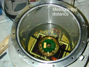
- Measure the oil level in the transformer tank. It should be no more than 6 3/4" below the flange surface (and not much less). Add new oil if necessary.
- Lower the magnet and klystron carefully into the tank, keeping an eye on the oil level in the transparent tube. The klystron setup is designed to work with the klystron output waveguide located opposite the umbilicus connector, so rotate if you need.
- When you still have a few inches to go, attach the reservoir to the tube and hold it in place by hand. Even if the final oil level is below the reservoir, it will probably spurt up the tube when the seal is first made. If you are worried about oil overflow, let a little out from the top valve.
- Insert bolts to guide you over the last inch or so.
- Tighten bolts. You are done.
- Some adjustment of the klystron position and angle is likely to be required to make the waveguide connection. Be careful---the tube doesn't lift straight.