Click image for enlarged view.
This document describes the laser transport system which provides the UV drive pulse for the cathode of the electron photoinjector.
Contents:
The purpose of the laser transport system is to provide UV photons at the cathode of the 1.6-cell photoinjector gun. The source of the laser energy is an Antares 76-S Nd:YAG laser located on the optical table in the Neptune Laser Room, which produces about 1W of laser power at 1064 nm wavelength. The IR is coupled into a 500m optical fiber producing a frequency chirp on the beam. The chirped pulse is then amplified in a regenerative amplifier, and is compressed by reflection from a grating which removes the frequency chirp. The laser pulse is then up-shifted in frequency by a doubling crystal to a wavelength of 532nm (Green). The green pulse leaves the Laser Room through an evacuated transport tube and is directed into the Bunker through a hole in the bunker ceiling. Upon reaching the laser table inside the bunker, the green is up-shifted again by another doubling crystal to produce a 50 to 100µJ pulse of UV at 266nm wavelength. The UV is then directed onto the "cathode mirror" inside the beamline, which reflects it onto the center of the cathode.
Click image for enlarged view.
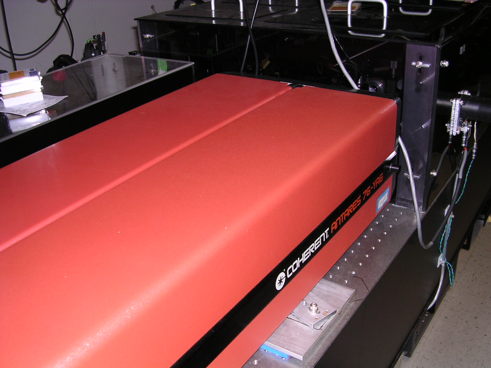
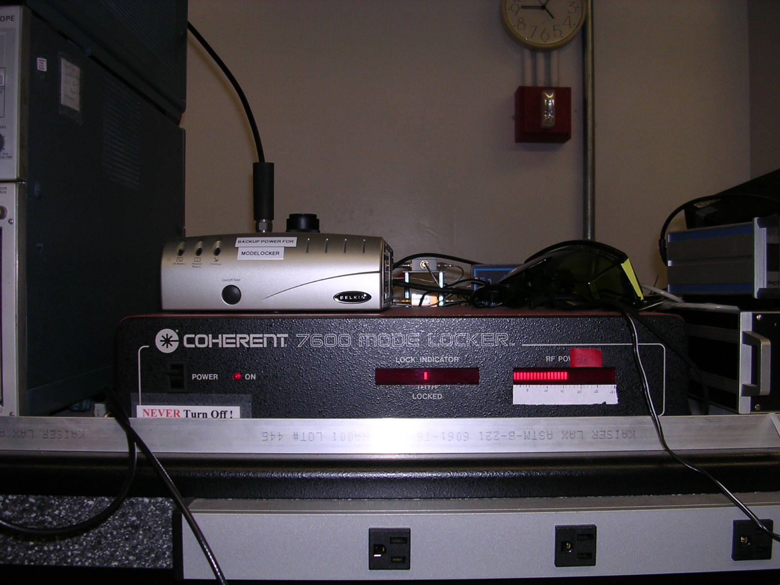
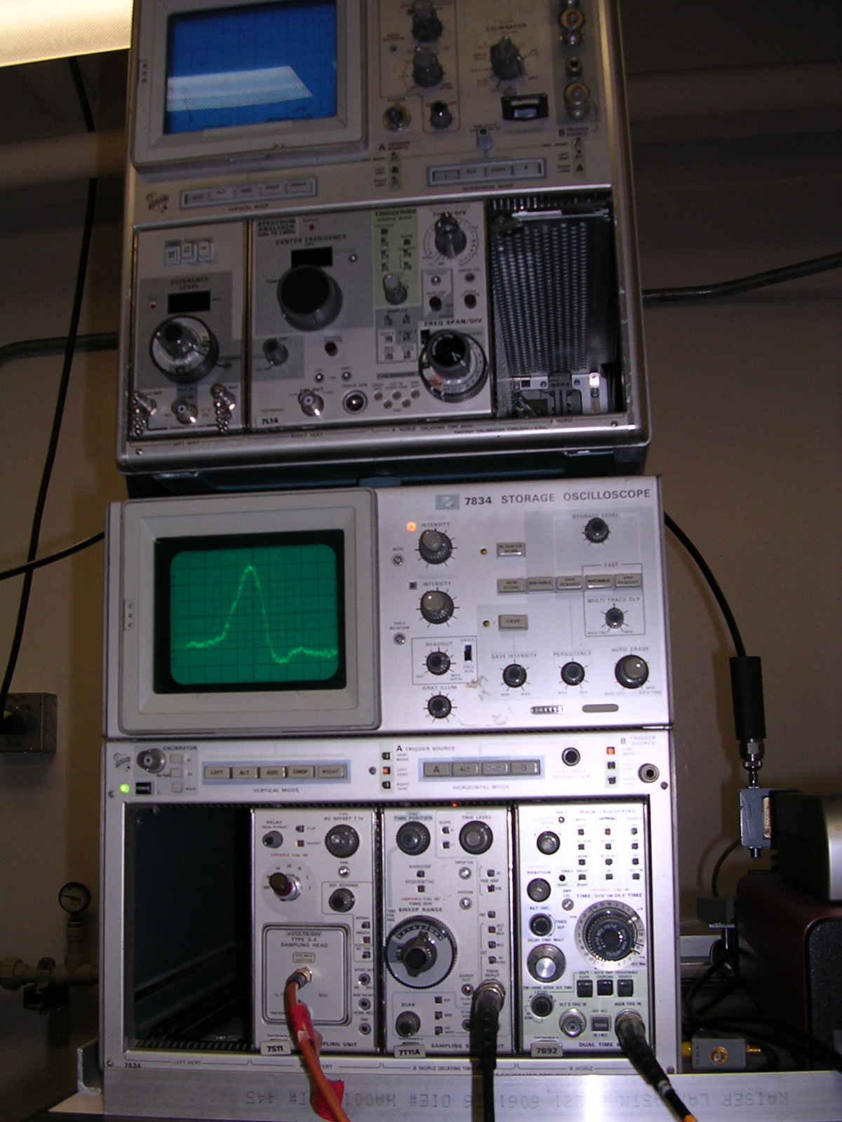
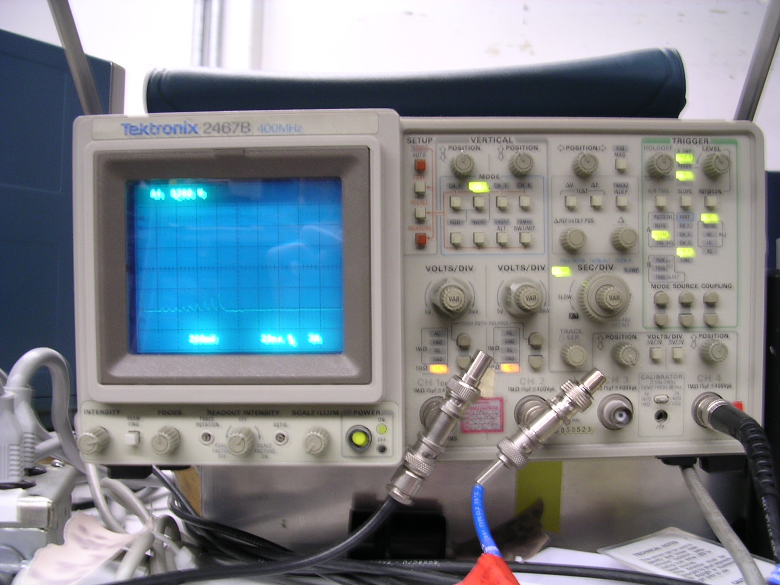
The Coherent Antares 76-S laser, operating in pulsed mode, puts out up to 22 Watts of power in TEM mode (0,0) at 1064 nm wavelength. The laser cavity is gold plated and shaped (in transverse cross-section) like two ellipses sharing a common focus. The Nd:YAG rod is located at the common focus and krypton arc lamps are located at the other two foci. The lamps are driven by a 32kV discharge provided by a high-voltage ignition pulse on an igniter board in the laser head. Pulsing of the laser is achieved by way of the Coherent 7600 mode-locker contained inside the laser case. The mode-locker consists of a Piezoelectric Transducer (PZT) bonded to an acoustically resonant optic. The PZT is driven at 38.08 MHz (the resonance frequency of the optic) by an external Coherent 7600 Mode-locker Driver, producing a resonant acoustic standing wave at this frequency in the optic. [Note: The Mode-Locker Driver should never be turned off. Once turned off and back on, the driver must relocate the PZT resonance. This may result in as little as a few hours or as much as a week or more of downtime. In some cases, it has been necessary to manually bypass the internal logic of the driver and hone-in on the resonance by hand.] The acoustic resonance results in a periodic diffraction loss at twice the driving frequency (since one RF period corresponds to two minima in the diffraction loss), resulting in laser output that is pulsed at 76.16 MHz, with each pulse being around 100ps FWHM. Output pulse length is monitored by a fast photodiode (Model AR-S3) which intercepts the beam from the secondary port and is read on the oscilloscope using a Tektronix 7S11 Sampling Unit, with a sampling rise time of 25ps.
Transport of the radiation emitted by the Antares laser to the regenerative amplifier, grating compression of the amplified pulse, and frequency up-conversion to green (532 nm) are accomplished by the optical components on the laser table in the Neptune Laser Room. A full-size schematic of the layout of the laser table optics can be viewed by clicking on the image below.
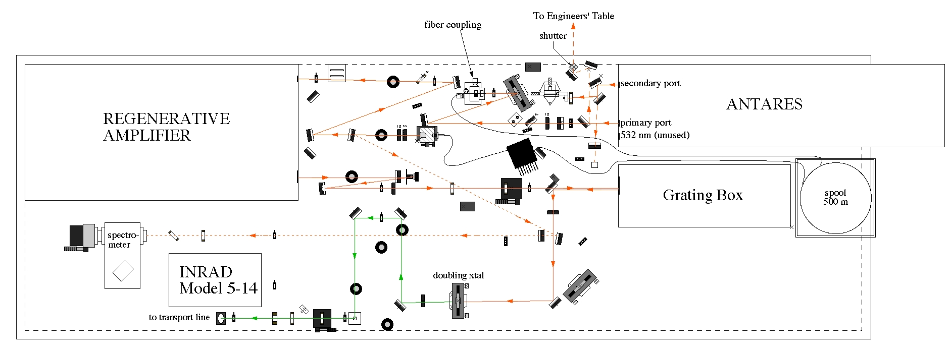
Laser Table Optics. Click image for enlarged view.
Infrared radiation is emitted from the Primary Port on the Antares 76-S. It is then coupled by an objective lens on a 3-axis manual stage into a 500 meter optical fiber spool, which chirps and broadens the pulse to about 200 ps FWHM. The fiber transmission is generally around 25-35%. Laser damage to the tip of the fiber on the input coupler side can result in reduced transmission. This may be corrected by re-cutting the tip of the fiber, for which purpose a diamond fiber cutting tool was purchased in 2004. After leaving the fiber through the output coupler, the laser beam passes through a 1/4 and a 1/2 waveplate to linearize the polarization and is then injected into the Regenerative Amplifier.
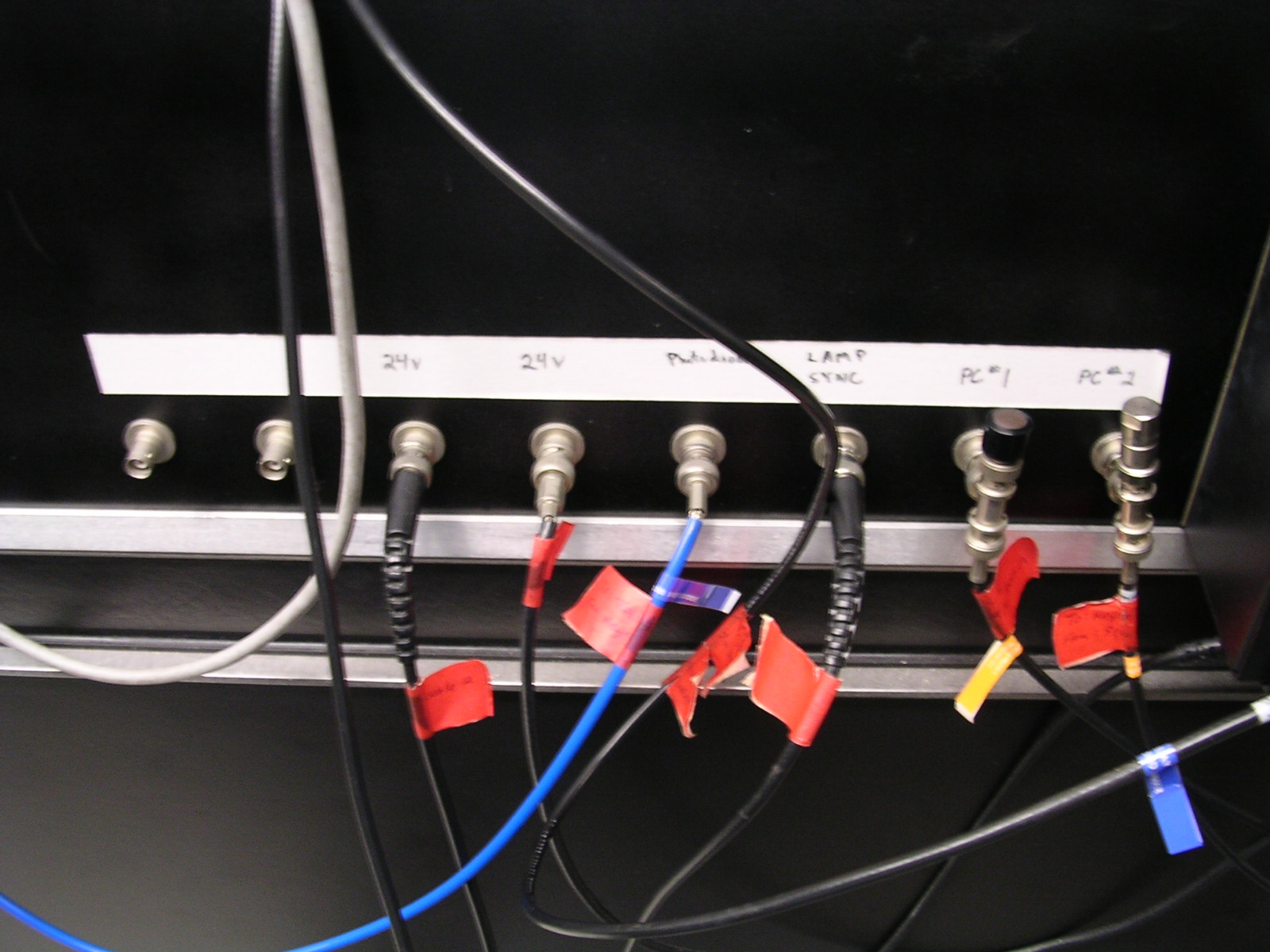
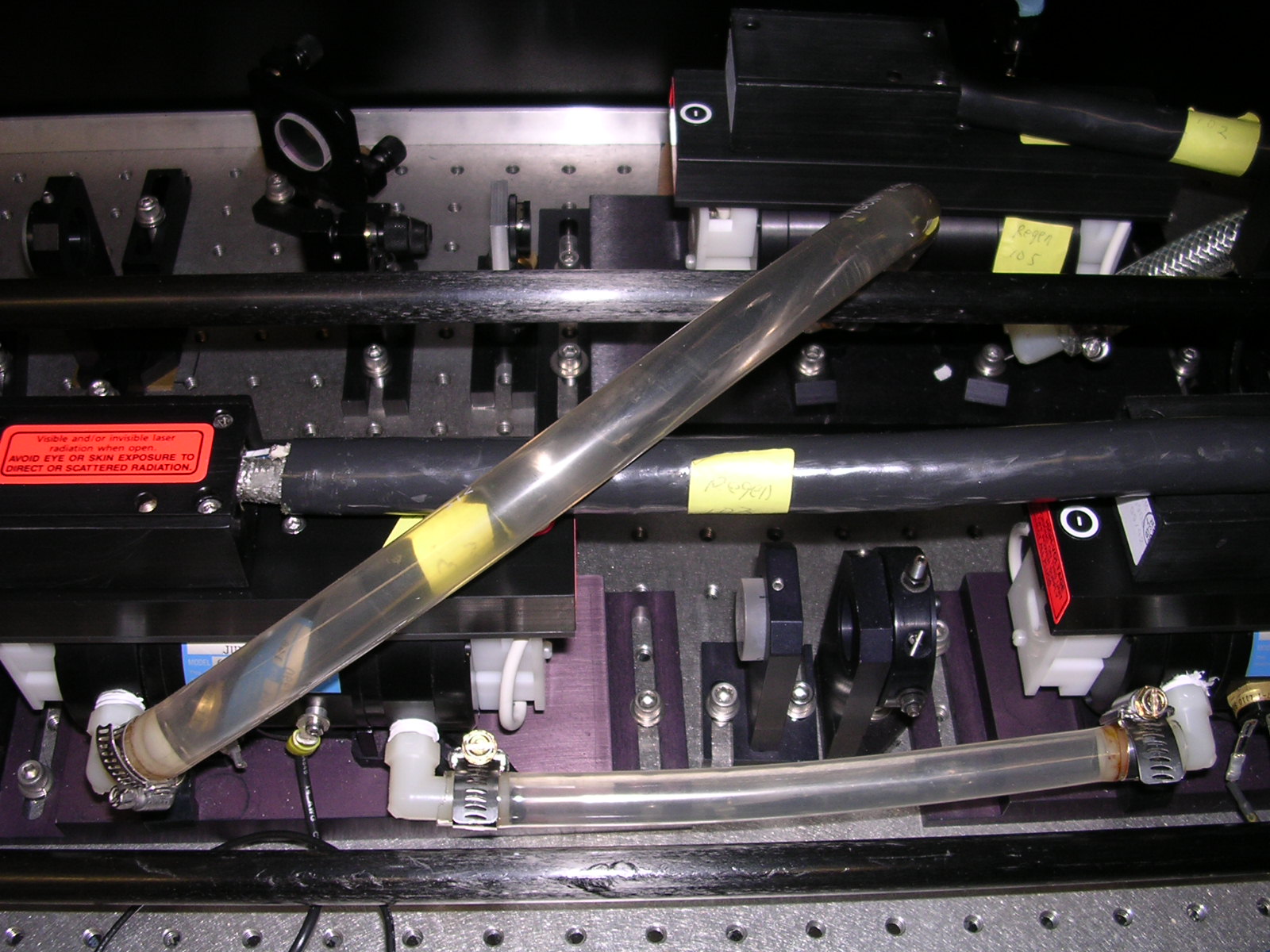
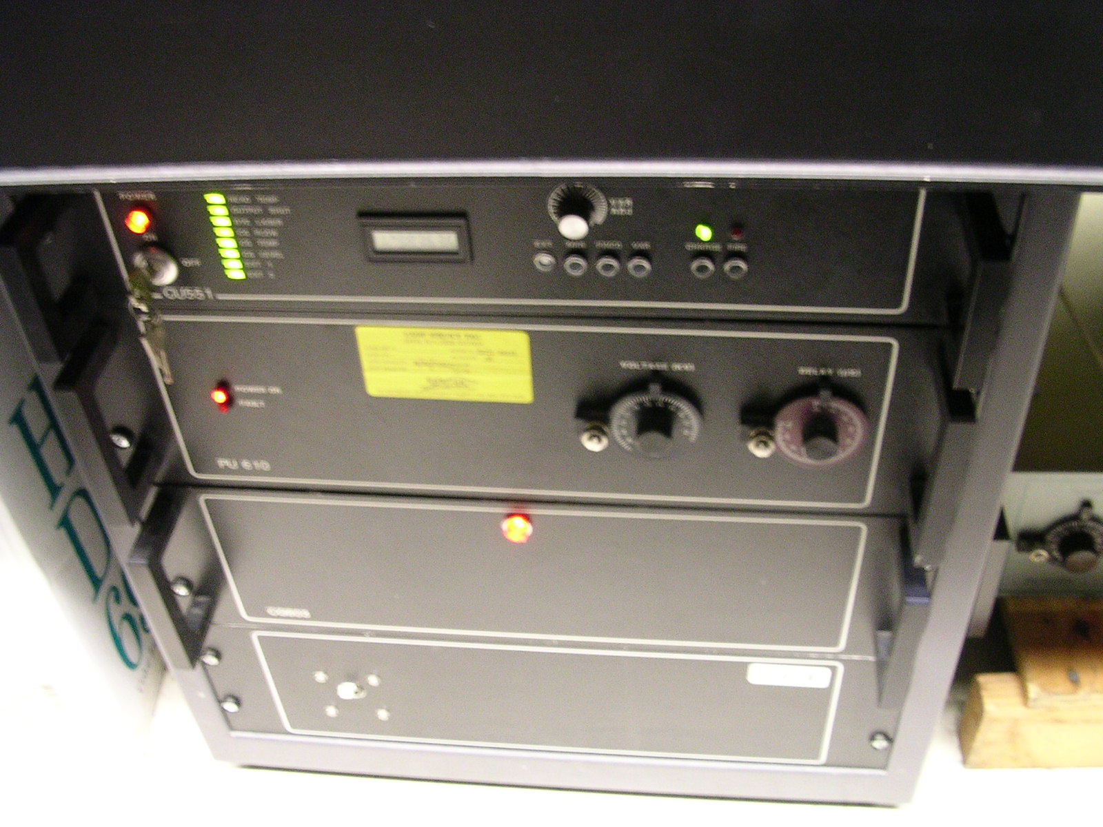
Once every 1/5 second the Continuum Regenerative Amplifier selects out a single pulse from the 76.16 MHz IR pulse train produced by the Antares 76-S and amplifies it over the course of multiple passes through the oscillator. The Regen oscillator consists of two Nd:glass rods, each pumped by two flashlamps (Continuum Part Number 203-0017, or Kentek Part Number LQY-2). The input pulse is selected by Pockels Cell #1. It then undergoes several passes through the oscillator until the pulse amplitude becomes maximized and is ejected by Pockels Cell #2. The bleed-through on one mirror of the oscillator is measured by a fast photodiode, which is displayed on the oscilloscope above the Regen. The scope trace shows a train of pulses building in amplitude and separated in time by 7ns, corresponding to successive passes through the oscillator prior to the ejection of the pulse. The timing of the two Pockel Cells can be adjusted using Stanford Box 1 channels A and B. In particular by adjusting the delay of the Pockel Cell #2 trigger using Stanford Box 1, Channel B, while simultaneously observing the photodiode signal on the scope, the pulse may be selectively ejected on the pass where its amplitude is maximum. If the trigger for Pockel Cell #2 is removed (by disconnecting the BNC on the trigger input labelled "PC#2") the pulse becomes trapped in the regen and the photodiode signal shows the entire train of reflected pulses as they grown in amplitude and then decay. The Regen enclosure contains a total of 3 lamp heads (2 in the oscillator and 1 in the 2-pass amplifier... see pic. The regen lamps must be replaced approximately every 20 million shots. The shot number is indicated on a counter on the Regen power supply controller. It is possible to change the regen lamps in such a way as to require minimal realigment of the Regen optics. The base plate for each lamp head contains a large thumb-screw which unscrews a single bolt that holds the lamp head in place. To remove the lamp head, disconnect all cables (in accordance with the Regen manual), and loosen the thumb-screw. Do not unbolt the base from the table! Also note that if the Kentek LQY-2 lamps are used, the teflon coating near the terminals must be removed before installation. This is most easilly accomplished by heating the teflon with a heat gun until the teflon becomes soft and then slide it off with pliers. Typical output of the Regen (after the 2-pass amplifier) when properly aligned is 15 to 20 mW average power (or 3 to 5 mJ per pulse). Lamp replacement will generally produce a boost in Regen output. In addition, more power can be obtained by slightly increasing the High Voltage on the two high voltage power supplies feeding the regen lamps. A typical value for the HV settings is about 1.34 kV. It is not advisable to exceed 1.4 kV as the electronics and/or optics may be damaged. Also, if the HV is to be increased in order to improve the output of the Regen, it is advisable to increase only the voltage on the amplifier power supply if possible, since the optics there are exposed to less total photon flux than those in the oscillator.
The grating box contains a pair of gratings on slide rails and a mirror. The chirped laser pulse from the Regen enters the grating box through a hole in the side. It reflects from one grating then the other, then reflects from the mirror, and retraces its path (although displaced vertically by about 1cm) and then exits through the same hole where it entered. The first order phase dispersion of this trajectory through the gratings produces a frequency dependent path delay. If the spacing of the gratings is chosen correctly, then this frequency dependent path delay entirely or partially removes the (approximately) linear chirp on the laser pulse, thereby compressing it to from 1 to 50 ps FWHM. The spacing of the gratings (and therefore the amount of compression) can be adjusted by repositioning one of the gratings on the slide rail. Note that after doing this, the downstream optics may require realignment.
After exiting the grating box, the IR laser pulse can be diverted from its normal path through the KDP conversion crystal, and be directed instead to the Second Harmonic Generation Autocorrelator by placing the prepared mirror setup onto the magnetic base located in the beam path before the crystal holder. The SHG Interferometer splits the laser pulse into two pulses at an infrared beam splitter and then recombines them at a critical angle inside of a large-aperture KDP crystal. Through second harmonic generation, a pulse of green is produced at the exit of the crystal, the amplitude of which is proportional to the autocorrelation function of the incident IR pulse. Measuring the amplitude of the green pulse as a function of the position of the mirror stage on the delay arm of the interferometer, one can reconstruct the autocorrelation function of the original pulse, and thereby deduce the pulse length. The amplitude of the green pulse is measured by a photodiode connected to an oscilloscope. To do a quick-and-dirty measurement of the FWHM of the IR laser pulse, adjust the delay arm until the green signal is maximized. Then move the delay arm until the signal is reduced by half. Subtract the two stage positions, multiply by two, and then divide by the speed of light. For a more detailed description of the Neptune SHG Interferometer, see the following technical note: Neptune Second Harmonic Generation Autocorrelator.
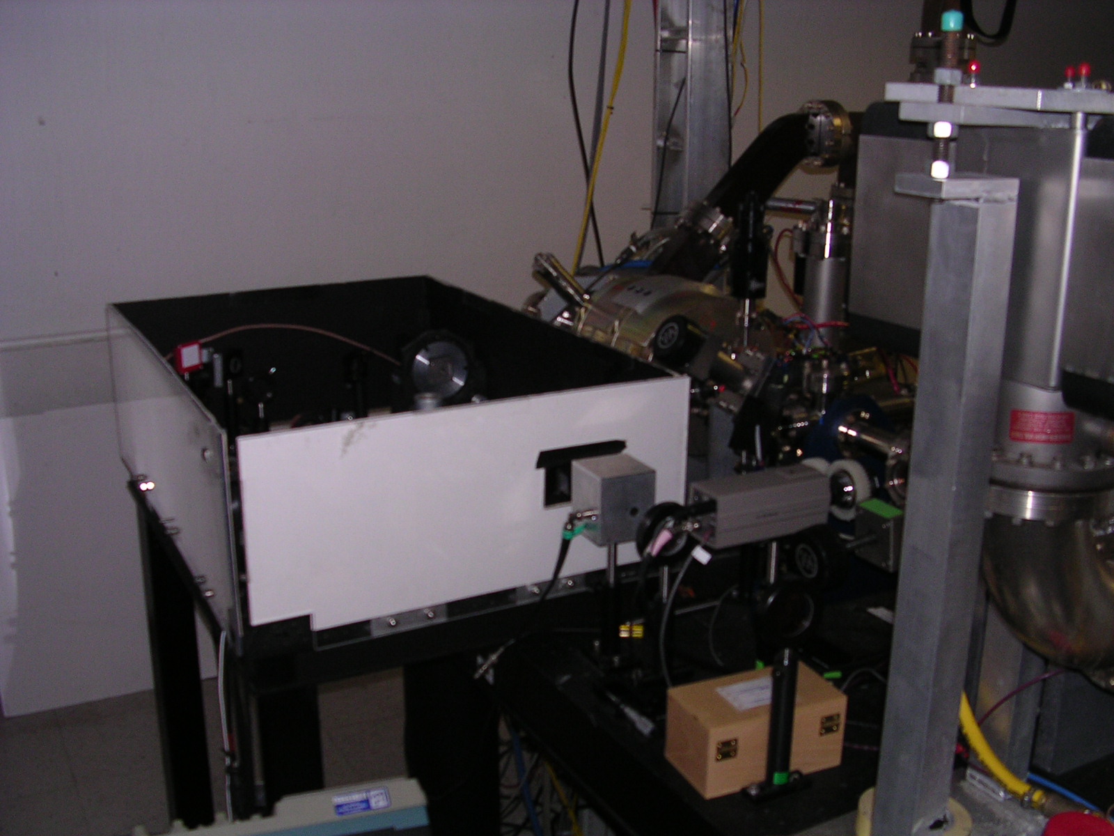
After passing though the conversion crystal, the IR pulse is upconverted to green (532 nm). It then reflects from 3 standard mirrors and a green polarizing cube (which sets the polarization and removes any remnant IR). The green laser pulse then passes through a 1/2 wave plate (to adjust the polarization angle) and is then reflected upward into the enclosed tranport line. The transport line consists of 5 vacuum boxes containing mirrors and lenses, connected by solid pipes. Their purpose is to transport the green laser pulse to the bunker with minimal loss of laser energy. Typical losses in the transport line are on the order of 60%. For doing minor adjustments to the alignment to improve transmission through the transport line, make sure that the beam is approximately centered on the iris before the final mirror on the laser table, and the external iris on the port on the first transport line box located in the laser room. When properly aligned, the laser spot on the mirror in the second box (located underneath the catwalk) should be located slightly off-center at a position corresponding to 9 o'clock when viewed from a direction looking toward the laser room. In the third box (located on top of the bunker) the laser should be centered on the lenses. The mirrors in the fourth and fifth boxes (located on the ceiling inside the bunker) can be adjusted if necessary so as to maximize the signal on a power meter placed on the beamline table at the exit of the transport line. Note that the air conditioning vents in the bunker should not be allowed to blow directly onto any portion of the transport line. This has been observed to cause periodic contractions of the connecting pipes, thereby producing a periodic misalignment (with a period corresponding to the cycle time of the A/C) which can result in a decrease in final UV energy by as much as 50%. Note also, that the transport line can potentially be evacuated to rough vacuum using the pump on top of the bunker. This has not traditionally been done for fear that the contraction of the pipes, etc. would produce misalignments. It is advisable, however, to keep all of the boxes on the transport line closed and sealed, in order to minimize air currents and collection of dust on the optics.
Click image for enlarged view.